
RIS-Aided Cell-Free Massive MIMO Systems for 6G: Fundamentals, System Design, and Applications
Published in arXiv, 2024
Abstract: Extremely large-scale multiple-input multiple-output (XL-MIMO) is a promising technology for the sixth-generation (6G) mobile communication networks. By significantly boosting the antenna number or size to at least an order of magnitude beyond current massive MIMO systems, XL-MIMO is expected to unprecedentedly enhance the spectral efficiency and spatial resolution for wireless communication. The evolution from massive MIMO to XL-MIMO is not simply an increase in the array size, but faces new design challenges, in terms of near-field channel modelling, performance analysis, channel estimation, and practical implementation. In this article, we give a comprehensive tutorial overview on near-field XL-MIMO communications, aiming to provide useful guidance for tackling the above challenges. First, the basic near-field modelling for XL-MIMO is established, by considering the new characteristics of non-uniform spherical wave (NUSW) and spatial non-stationarity. Next, based on the near-field modelling, the performance analysis of XL-MIMO is presented, including the near-field signal-to-noise ratio (SNR) scaling laws, beam focusing pattern, achievable rate, and degrees-of-freedom (DoF). Furthermore, various XL-MIMO design issues such as near-field beam codebook, beam training, channel estimation, and delay alignment modulation (DAM) transmission are elaborated. Finally, we point out promising directions to inspire future research on near-field XL-MIMO communications. Index Terms: Extremely large-scale MIMO, near-field modelling, non-uniform spherical wave, spatial non-stationarity, near-field SNR scaling law, beam focusing pattern, near-field codebook, near-field beam training, near-field inter-user interference
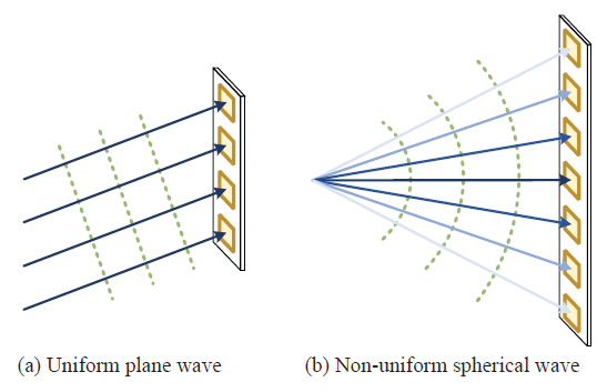
Fig. 2: Illustration of far-field UPW versus near-field NUSW.
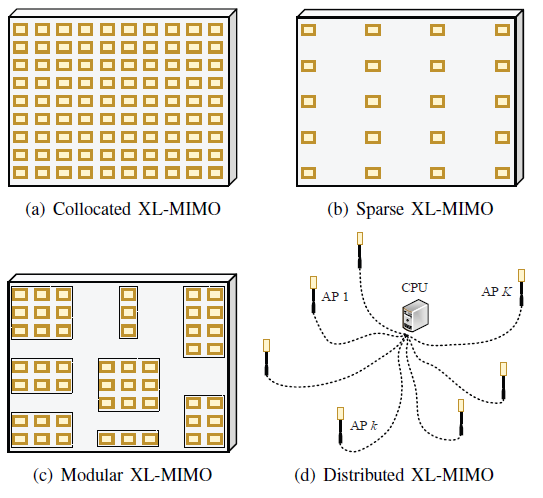
Fig. 3: Different architectures of XL-MIMO.
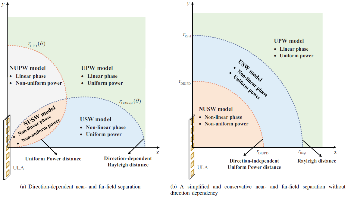
Fig. 9: An illustration of the refined near- and far-field separation, where the ULA is placed along the y-axis, with its center located at the origin. Due to symmetry, only the first quadrant is shown.
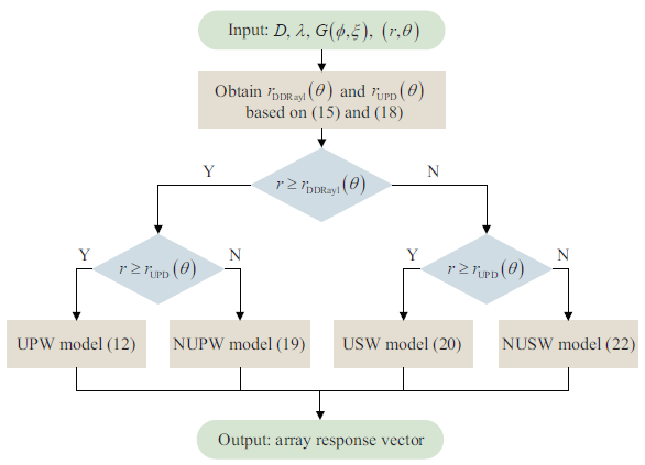
Fig. 10: Summary of near-field array response vector modelling.
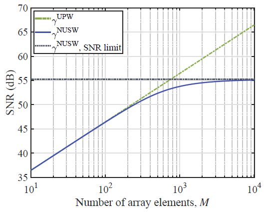
Fig. 17: SNR versus the number of antenna elements M with NUSW and UPW models [9].
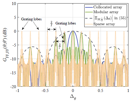
Fig. 19: Comparisons of far-field beam pattern for collocated, modular and sparse array architectures.
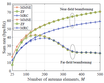
Fig. 22: Sum rate versus the antenna number M for near- and far-field MMSE, ZF, and MRC beamforming.
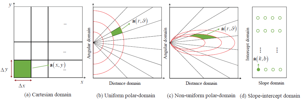
Fig. 23: Illustration of different near-field beam codebook designs.
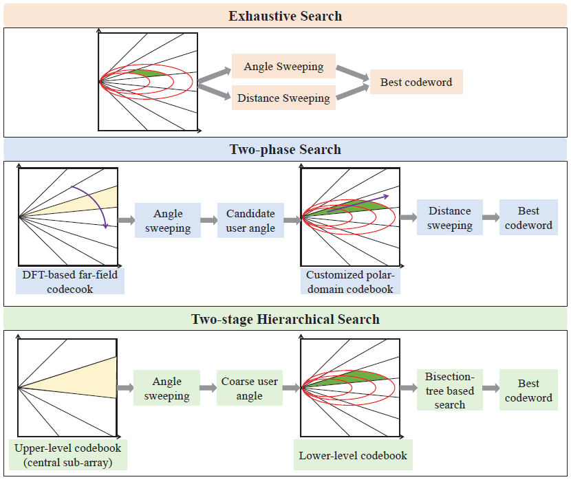
Fig. 24: Illustration of different near-field beam training methods.
Recommended citation: Haiquan Lu, Yong Zeng, Changsheng You, Yu Han, Jiayi Zhang, Zhe Wang, Zhenjun Dong, Shi Jin, Cheng-Xiang Wang, Tao Jiang, Xiaohu You, and Rui Zhang, "A Tutorial on Near-Field XL-MIMO Communications Towards 6G," arXiv:2310.11044, 2023. [Download paper here](https://zhewang77.github.io/files/A tutorial on near-field XL-MIMO communications towards 6G.pdf) https://arxiv.org/abs/2310.00263